Hardware Overview
The robot consists of core hardware systems that work together to enable the robot to move and perceive its surroundings effectively. The hardware is divided into:
- Structure
- Motors and Wheels
- Motor Drivers
- Control Board
- Power Supply
- Additional Accessories
Structure
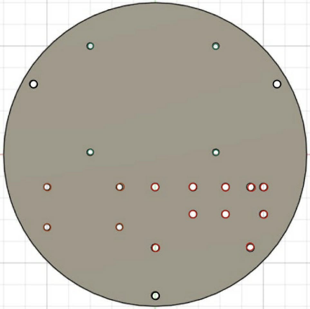
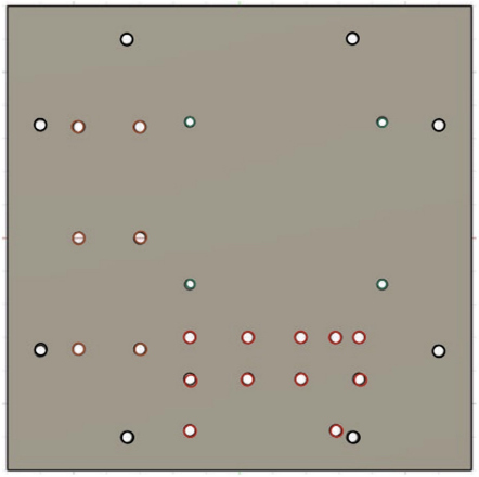
The robot structure in this project is designed in a Blueprint format, allowing users to manufacture the robot frame on their own. The provided Blueprints can be used to cut from various materials such as acrylic sheets, metal sheets, plywood, or other materials as appropriate.
The structure is designed to be flexible, supporting robot assembly with different drive configurations — from 2-wheel, 3-wheel, to 4-wheel setups. In total, 8 different robot configurations can be assembled from the Blueprints:
- Blueprint for rectangular 2-wheel robot
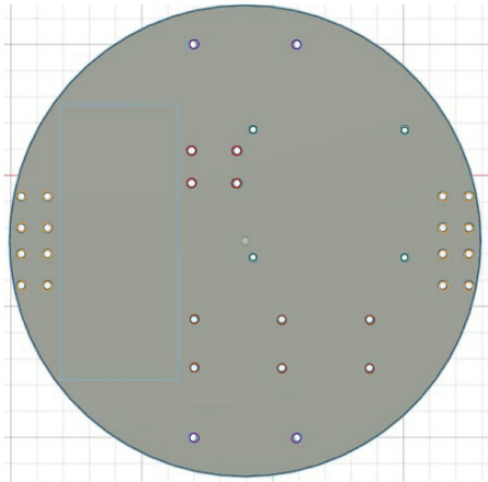
- Blueprint for circular 2-wheel robot
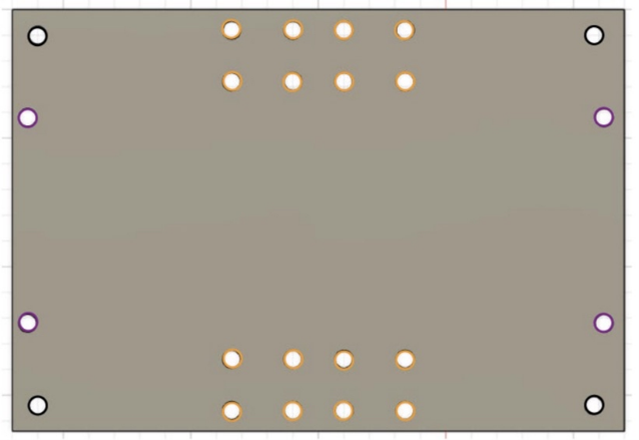
- Blueprint for rectangular 2-wheel double-decker robot
- Blueprint for circular 2-wheel double-decker robot
- Blueprint for 3-wheel robot
- Blueprint for 3-wheel double-decker robot
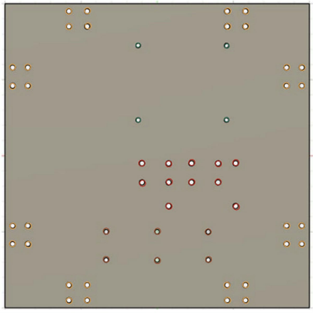
- Blueprint for 4-wheel robot
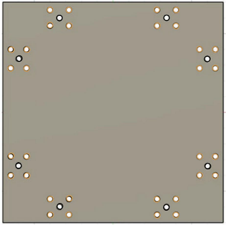
- Blueprint for 4-wheel double-decker robot
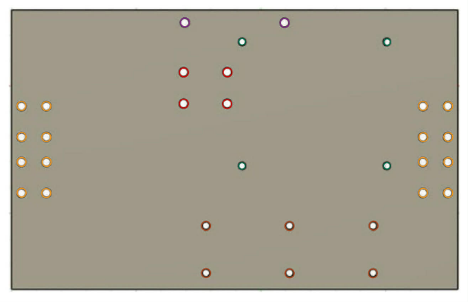
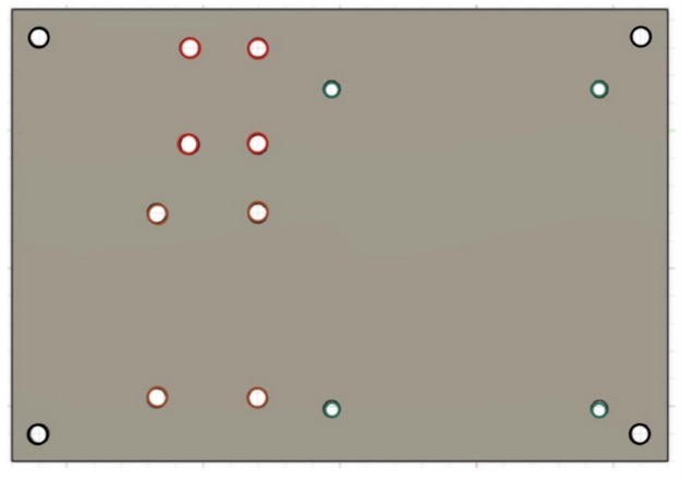
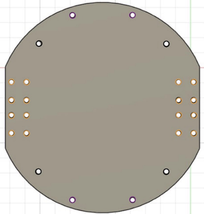
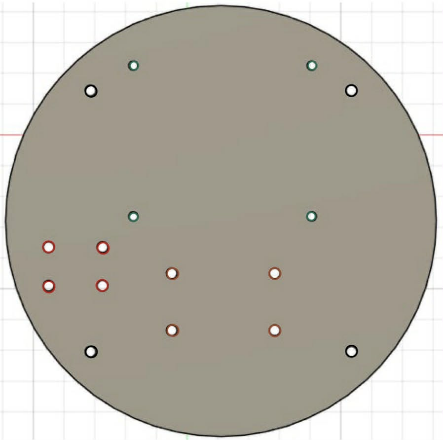
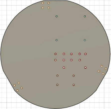
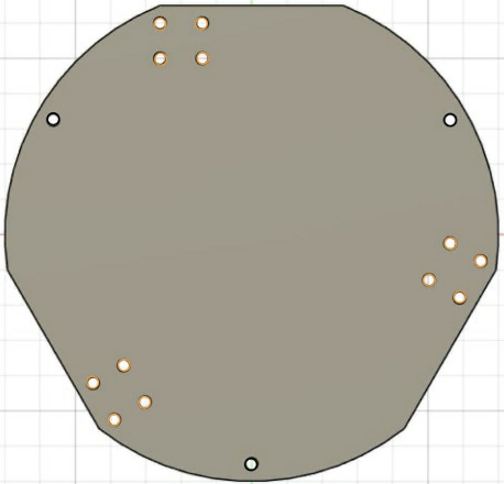
The Blueprints use color-coded mounting holes to help beginners easily identify where to install each component:
| Color | Purpose |
|---|---|
| 🟡 Yellow | Mounting holes for motors |
| 🔴 Red | Mounting holes for motor drivers |
| 🟢 Green | Mounting holes for PCB board |
| 🟣 Purple | Mounting holes for caster wheel |
| 🟤 Brown | Mounting holes for Step Down Converter |
| ⚫ Black | Mounting holes for standoff posts (double-decker robots) |
Note: All mounting holes are designed based on the equipment used during actual testing. If you use different components with different mounting positions, you can:
- Use double-sided tape to attach components to the structure
- Design and modify your own structure using the provided Blueprints as a reference
Motors and Wheels
Motors
This project uses TT Motors (DC Gear Motors), which are popular in beginner robotics due to their low cost, easy assembly, and wide availability. They come in two types:
-
TT Motor without Encoder
- Drives the wheels directly through rotation
- Simple structure
- Easy to control
- Suitable for learning basic robot movement
- Ideal for children and beginners
- Cannot accurately measure speed or distance traveled, but sufficient for basic experiments and learning
-
TT Motor with Encoder
- Includes an encoder to detect the number of motor rotations
- Can measure speed and distance traveled
- Enables more precise movement control
- Suitable for advanced control applications
Users can choose either motor type based on their skill level and intended use.
Wheels
This project supports multiple wheel types to suit different robot movement configurations:
-
Rubber Wheels (Differential Drive)
- For 2-wheel and 4-wheel robots
- Moves forward/backward and turns left/right
- Easy to understand
- Ideal for beginners
-
Omni Wheels
- For 3-wheel robots
- Can move in multiple directions
- Smoother movement
- Suitable for learning multi-axis movement systems
-
Mecanum Wheels
- For 4-wheel robots
- Can move in all directions — forward, backward, sideways, and diagonally
- Ideal for movement in tight spaces
- Advanced movement configuration
-
Caster Wheel / Ball Wheel
- Used as a support wheel to maintain robot balance
- Not connected to any motor
- Rotates freely in all directions
- Improves robot stability
- Used with 2-wheel robots
Motor Drivers
For motor control, this project uses the L9110S Motor Driver — a Dual H-Bridge driver suitable for small DC motors like TT Motors.
L9110S Features:
- Controls motor rotation direction (forward / reverse)
- Speed control via PWM signals
- Simple circuit design, ideal for beginners
- Low voltage operation, safe for experiments
- Available configurations:
- 2-motor control (for 2-wheel or 3-wheel robots)
- 4-motor control (for 4-wheel or 3-wheel robots)
Matching the number of L9110S inputs to the number of motors simplifies system design and allows flexible drive configuration changes.
Control Board
This project features a custom-designed Printed Circuit Board (PCB) that simplifies wiring and device connections. The PCB is designed to work with both the ESP32 microcontroller and Raspberry Pi 5 single-board computer on the same board.
The PCB provides slots for two ESP32 form factors:
- ESP32 DevKitC
- ESP32 NodeMCU
These have different sizes and pin spacing, allowing users to choose the appropriate controller board.
The PCB is divided into the following main sections:
- Power Section — Receives power from the battery
- Control Section — Connects the microcontroller to motor drivers and other devices
- Status Section — LED indicators showing system status
| LED | Meaning |
|---|---|
| 🔴 Red | Power supply / battery connection status |
| 🟢 Green | Wi-Fi network connection status — active when connected to Raspberry Pi |
| 🟡 Yellow | System running status — active when connected to Raspberry Pi |
| ⚪ White | Auxiliary status LED — reserved for future use or system expansion |
The PCB mounting holes are designed to align with Raspberry Pi 5, enabling easy and secure co-installation on the same structural base.
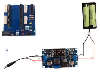
Power Supply
The system is designed to work with various small, lightweight power sources that output 5 volts (5V).
- 18650 Lithium-Ion Battery — Popular, compact, and lightweight. Requires a Step-Down converter to reduce voltage to 5V.
- AA Batteries — Easy to find, suitable for basic experiments and learning. Can be wired in series with a Step-Down converter.
- Power Bank — Convenient, most already output 5V and can be connected directly.
- Li-Po (Lithium Polymer) Battery — High current output, lightweight. Should be used with a Step-Down converter and proper safety precautions.
- Other Power Sources — Any power source that can provide 5V with sufficient current for the system.
Additional Accessories
To enhance the robot's capabilities, additional accessories can be installed as needed:
- Step-Down Module (DC-DC Converter) — Reduces voltage to safe levels for each component, preventing damage from overvoltage.
- Raspberry Pi 5 — A small computer board for image processing, artificial intelligence (AI), network-based control, and autonomous navigation.
- Camera Module — Adds vision capabilities such as object detection, line tracking, and face recognition when used with Raspberry Pi.
These accessories can be selected and installed based on your project's goals, making the robot flexible and expandable for more complex applications.
Robot Assembly
The robot assembly process is designed to be flexible. You can follow the recommended order or adjust steps as needed.
1. Choose a Robot Base from the Blueprints
Start by selecting a robot base Blueprint based on your desired movement type (2-wheel, 3-wheel, or 4-wheel). Then cut the frame from your chosen material.
2. Attach Motors to the Structure
Mount TT Motors (with or without Encoder) to the mounting holes on the structure as indicated by the Blueprint.
3. Install Wheels
Install wheels appropriate for your chosen base:
- 2-wheel & 4-wheel bases → Differential Drive rubber wheels
- 3-wheel base → Omni wheels
- 4-wheel base → Mecanum wheels (optional)
- Add a Caster Wheel for additional balance support if needed
4. Install Motor Driver Board
Mount the L9110S motor driver board on the structure using the designated mounting holes.
5. Install the PCB
Install the custom PCB designed for this project, which simplifies wiring and device connections.
Note: The assembly steps above are a recommended guideline. You can rearrange steps as needed, but always consider structural integrity and wire routing convenience.
Assembly Video
Watch the full assembly tutorial on our YouTube channel:
🎬 AutOBot Assembly YouTube Channel
Electrical Connection
Wiring is a critical step. Work carefully to prevent equipment damage or safety hazards.
1. Check Power Supply First
Use approximately 5 volts (5V). If the voltage is higher, use a Step-Down converter first.
2. Turn Off Power Before Wiring
Always disconnect the battery or turn off the switch before connecting any wires.
3. Wire According to the Diagram
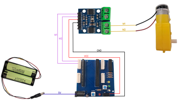
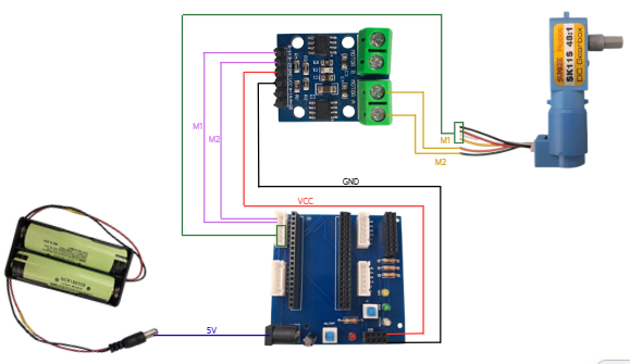
4. Check Wire Connections
Make sure all wires are secure and no exposed copper is visible, as this could cause a short circuit.
5. Double-Check Before Powering On
Ensure all connections are in the correct positions, no wires are touching incorrectly, and no metal contacts are exposed.
6. Power On and Check Status
After powering on, check the LED indicators on the board. If you smell burning or notice abnormal heat, disconnect the power immediately.